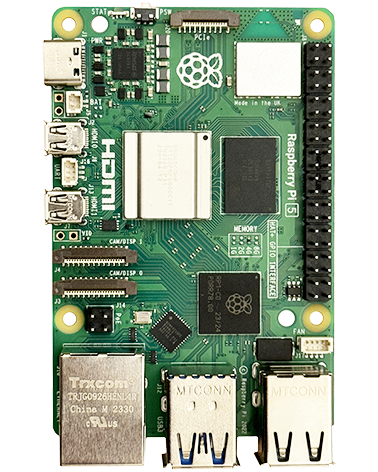
microUSB Power Input
Has a 1.1 A polyfuse (700mA "hold current").
RPi Power Consumption
Varies depending on how busy it is and what peripherals are connected.
Running a GUI and running the GPU will take extra power.
The USB devices and Ethernet connection will take power.
General usage
Reported current requirements of between 300mA and 550mA are typical for the model B, but it can take more, especially for short periods.
Maximum
From the Raspberry guys: "Model B owners using networking and high-current USB peripherals will require a supply which can source 700mA. Model A owners with powered USB devices will be able to get away with a much lower current capacity (300mA feels like a reasonable safety margin)."
USB Ports
Each of the two USB ports on the Pi has a polyfuse rated at 140mA. Note that polyfuses cause voltage drop when used at currents near their rating (their resistance increases) which can upset some USB devices if they rely on getting close to 5V.
The USB outputs are powered directly from the +5V rail via their polyswitch (see RPi schematic). Often the LAN9512 USB controller IC PRTCTL pins would be used with a USB power switch device to control power to a connected USB device, however on the RPi to remove this additional component cost, the PRTCTL pins simply monitor for power is being supplied. If the polyfuse trips for an output the +5V output pin will go low and pull PRTCTL low via its series diode, replicating the OC over current signal pin of a USB power switch.
If your device needs more current and you don't want to use a USB hub the following can be done:
Open the USB cable by removing the sleeving in a small area, open up the screen but don't cut it away completely (a couple of inches of open screen is unlikely to have any effect on performance as the USB data lines are balanced to reject interference.
Cut the +V connection (usually red)
Leave the data connection (usually white and green)
Cut the 0V / GND connection (usually black, sometimes blue)
Insulate the +V and 0V wires going to the RPi.
Connect the 5V power supply directly to the +V and 0V wires going to your USB device. If powering from a high current power supply (>1A) then add a fuse in series with the +V connection in case there was a fault with the USB device (e.g. use a 500mA or 1A polyfuse).
The only downside of this approach – the USB controller IC won't detect if the fuse ever trips. Not a particular concern as the fuse will only trip in an fault situation (assuming your 5V power supply can provide enough current for the device) at which point you've got a problem anyway.


5 years ago
I will do this, but internally… Unsoldering the USB and bending the two + leads before soldering it back. That prevents from powering backwards through USB. this solution accepts only externally powered USB devices.
Generally i want to follow the recommendations abowe, because I also want my RPI to also accept passive USB devices. The booth + leads should then go to the polyfuse (F3 on my ver B by soldering the wire to the lead nearest the edge, or probably by scratchig to bloat the cupper between the two holes near micro-USB and sold it there)
My question: Why is the 500 mA fuse / 1A polyfuse recommended?
I am not an engineer, so I wonder what happens if RPI is powered from both the micro-USB and by the USB – if it would happen? If one adapter is 1A and the other is 2A it results in 1.5 A. Can one adapter or device be damaged then? Better have same A on booth?
I am more sure that it can be powered either by the usual way (micro-USB) or by a powered USB-hub with that ability of powering backwards, for example :) All the USB + are soldered together!
I se no meaning of a fuse because it not affects my RPI. I will let the fuse burn in my adapter or the pluged devices. Would 500 mA really be enough for all USB-devices?