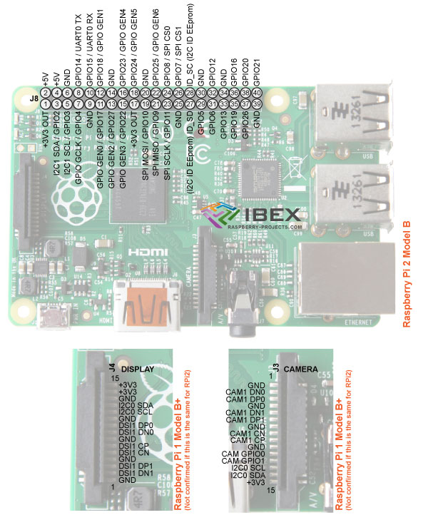
Note that the schematic for the Raspberry Pi 2 Model B has not been released so we are unable to confirm if there are any changes to the specific signals used on the display and camera connectors.
Changes Compared to Raspberry Pi 1
The Raspberry Pi 2 uses a new processor model so some pin additional functions may have changed.
The same GPIO pins are used for the Raspberry Pi 2 (e.g. GPIO2, GPIO3, etc).
The GND, +5V, +3V3, UART, I2C and SPI bus pins are in the same places.
The PWM specific pin is no longer marked as PWM and now 7 pins are marked as 'GPIO GEN0' to 'GPIO GEN6'.
IO Pins
All IO pins are 3.3V, not 1.8V. Pins are not 5V tolerant.
Full details are available here
Power-up State
Its likely all pins are set as inputs on power up (TBC).
I2C pins (e.g. Pj-3 and P8-5) are therefore high due to the pull up resistors on these pins.
I2C
Pull up resistors are included on the RPi board so are not needed externally (true for RPi1 Model B so presumably true for RPi 2 Model B, but not confirmed as full schematic not yet available).
Interfacing the RPi 3.3V I2C pins to a 5V device like an Arduino – see here.
SPI
The Chip Select signals are for up to two independent slave devices. It seems that with the SPI port enabled in Raspbian both the CS0 and CS1 pins are assigned to it and therefore can't be used as IO (our assumption – correct?)
3.3V / 5V Interfacing
See our other page here
ID_SD & ID_SC Pins
These are for an auto configuration eeprom which you can include on your RPi add on board and which Raspbian will read to detect the board connected. For more info see here.


