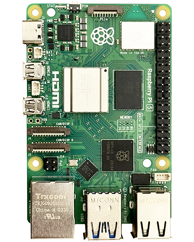
Hardware In simple terms the RPi Compute Module is a Raspberry Pi Model A without PSU etc circuitry, connectors and with a 4GB Flash IC instead of the SD card socket. On the PCB: BCM2835 processor with 512Mbyte of RAM (as used on the Raspberry Pi) 4Gbyte eMMC Flash IC, instead of the SD card used on […]
Category: Compute Module
Compute Module Documentation
Documentation for the Compute Module can be found here.
Compute Module IO Board
Overview An open-source breakout board that you can plug a Raspberry Pi Compute Module into. Provides a starting template for those who want to design with the Compute Module, and a quick way to start experimenting with the hardware and building and testing a system before going fabricating a custom board. Provides: Power to the module. […]
Compute Module IO Pins
Bank 0 GPIO GPIO0-27_VREF is the power supply for bank 0 and can be powered in the range 1.8V – 3.3V. (Must be powered even if GPIO is not used). GPIO0 / I2C0 SDA GPIO1 / I2C0 SCL GPIO2 / I2C1 SDA GPIO3 / I2C1 SCL GPIO4 / GPCLK0 GPIO5 / GPCLK1 GPIO6 / GPCLK2 GPIO7 / SPI0 CE1 GPIO8 / SPI0 CE0 GPIO9 / SPI0 MISO GPIO10 / SPI0 MOSI GPIO11 / SPI0 SCLK […]
Compute Module Schematics
Schematics for the Compute Module can be found here.
Programming The Compute Module
Installing the OS See the official guide here. First Time Use Of A Windows PC For Installing Onto The Compute Module Install CM-Boot-Installer.exe first so the USB drivers are ready to be used. When you connect the Compute Module development PCB (fitted with the CM) to your Windows PC for the first time you should see windows […]

